How to Size a Head and Tailstock
SELECTING A HEAD AND TAILSTOCK TO BEST MEET YOUR NEEDS
Head and Tailstock Positioners are used to support and rotate long or heavy weldments about a horizontal axis. Selecting the appropriate Head and Tailstock model depends the overhang of your work piece and maximum weight capacity required. The following descriptions and specifications provide a clear, logical checklist to help you select the right positioning equipment for your application.
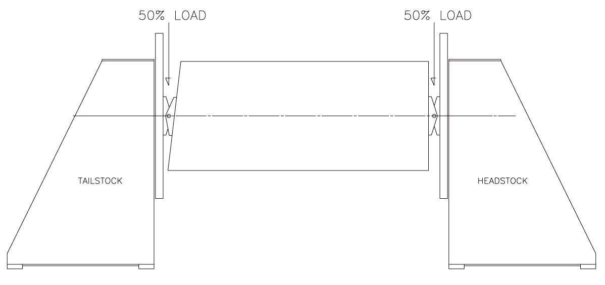
Weight Capacity and Load Distribution :
A typical configuration consists of one powered headstock, which provides rotation, and one non-powered tailstock, which supports the opposite end of the workpiece. Ideally, the load should be evenly distributed between the headstock and tailstock. If the center of gravity along the rotational centerline causes either unit to support more than half of the total load, a higher-capacity model may be required.
Model selections can handle a range between 2500-240,000 lb weldments.
Rotation Torque Requirements:
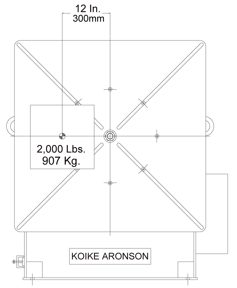
To calculate the weldment’s rotation torque load, multiply the weldment weight (in pounds) by the distance (in inches) from the center of the table to the weldment’s center of gravity.
This distance is measured parallel to the table surface. The resulting value must not exceed the maximum allowable torque listed in the “Rotation” column.
Note: Tailstocks with freewheeling tables do not require torque ratings.
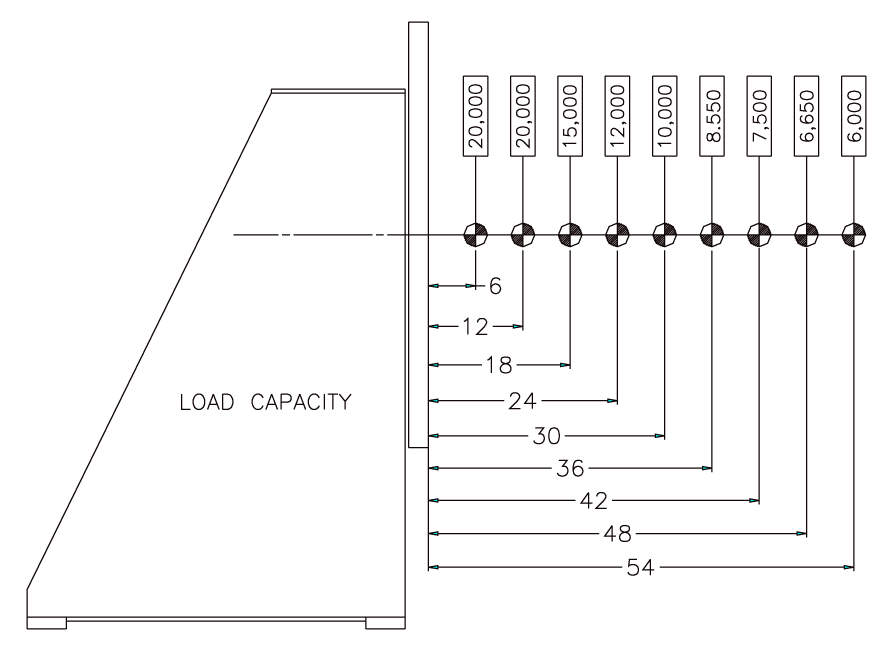
Overhung Loads:
Head and Tailstock units are rated for overhung loads.
To properly size the system, you'll need to determine the following:
• The total weight of the workpiece
• The distance the center of gravity is located ahead of the table face
When flexible mounting methods are used, the overhung load is determined by the distance from the table face to the flexible connection point. This distance should be kept as short as possible to minimize overhung load and ensure safe operation.
Fixturing and Mounting Considerations:
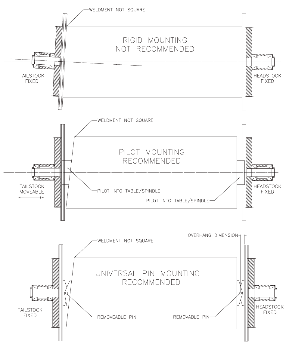
Rigidly mounting a workpiece between a headstock and tailstock should be avoided whenever possible. Misalignment or inaccuracies in the workpiece can introduce significant stresses, potentially damaging the equipment or creating unsafe conditions.
Flexible mounting methods are strongly recommended to relieve misalignment and reduce stress:
• Pilot mounting uses stub shafts to support the load while allowing limited movement
• Universal pin mounting provides flexibility without requiring tailstock repositioning
• Wobble plate mounting distributes load through drive dogs while accommodating misalignment
These methods reduce rotational drag, protect drivetrain components, and improve overall system reliability.
Properly sizing a Head and Tailstock system requires consideration of weight distribution, rotational torque, overhung loads, and mounting method. Understanding how these factors interact ensures smooth rotation, reduced stress on components, and safe, reliable operation.
If you have a specific workpiece or application in mind, our team can help review your requirements and recommend the appropriate headstock and tailstock configuration.
Looking to Size a Different Positioner?
Check out our other guides on how to size the right positioner to fit your needs!