How to Size a Positioner
SELECTING A POSITIONER TO BEST MEET YOUR NEEDS
Tilt/Turn Positioners provide powered rotation and tilt of a weldment to place it in the ideal position for downhand welding. Selecting the appropriate positioner depends upon the size and shape of the work-piece. These descriptions and specifications are made to give you a simple, logical checklist to successfully select the right positioning equipment for the right job.
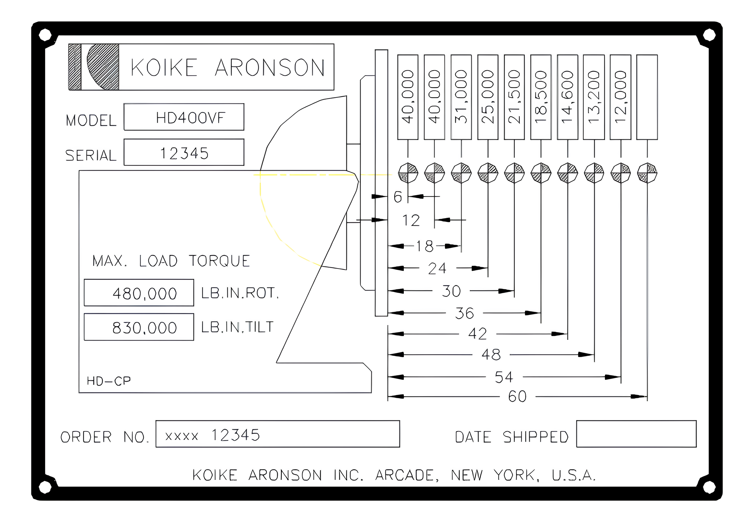
The illustration to the right shows a typical capacity plate installed on every gear-driven positioner.
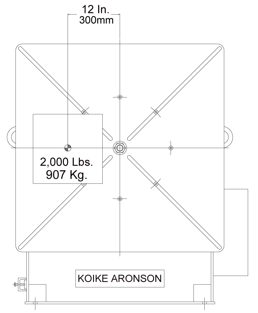
This example features the capacity plate for a Model HD400. The HD400 is rated to handle loads up
to 40,000 lb (18,140 kg) with the center of gravity located 12 in (300 mm) from the surface of the table.
All information needed to properly load the positioner is provided directly on the capacity plate or can
be easily calculated using the data shown below.
TORQUE LOADS
Tilt Torque Load
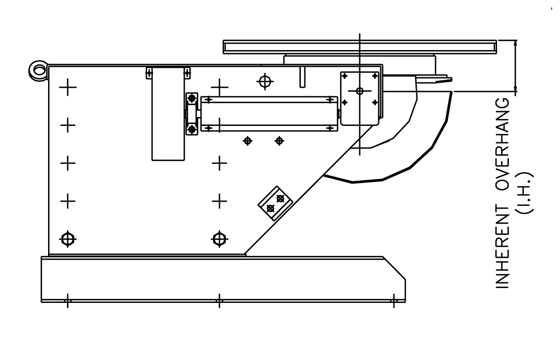
To determine the weldment’s tilt torque load, add the inherent overhang (in inches)
to the distance from the table surface to the weldment’s center of gravity.
This distance is measured perpendicular to the tabletop. Multiply the total distance by
the weight of the weldment to calculate the tilt torque load. The calculated value must
not exceed the maximum allowable tilt torque listed in the “Tilt” column.
Rotation Torque Load
To calculate the weldment’s rotation torque load, multiply the weldment weight (in pounds) by the distance (in inches) from the center of the table to the weldment’s center of gravity.
This distance is measured parallel to the table surface. The resulting value must not
exceed the maximum allowable torque listed in the “Rotation” column.
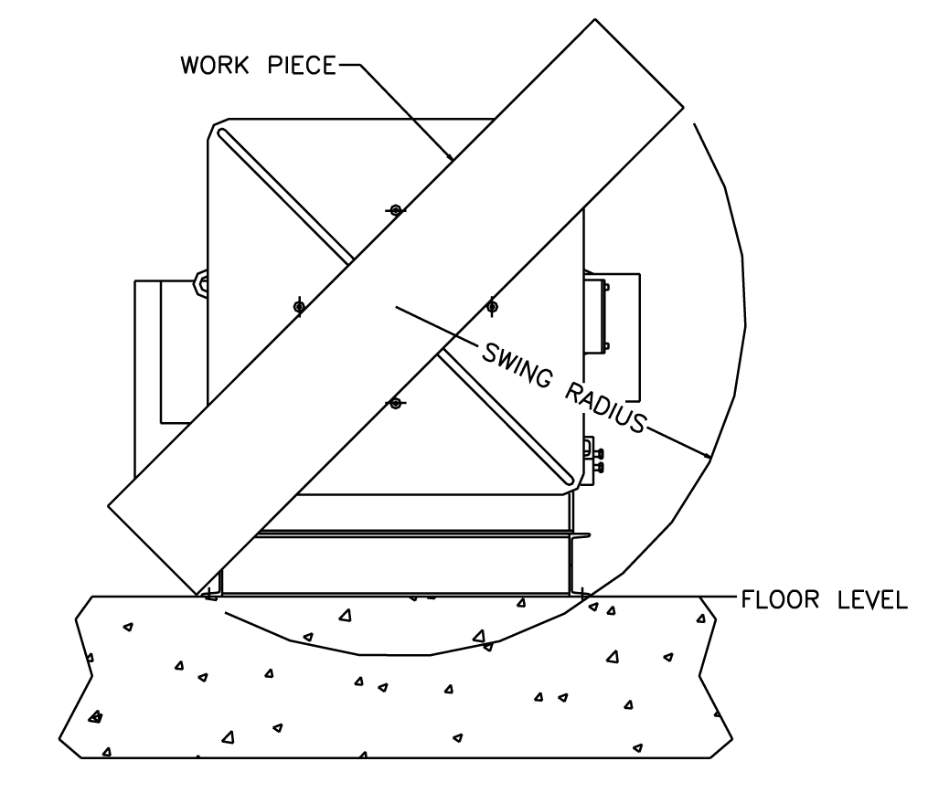
SWING RADIUS
When selecting a positioner, be sure to allow enough clearance for the workpiece to
swing above the floor when the table is fully tilted.
Overlooking swing clearance is a common mistake when specifying positioners. For
larger or taller workpieces, our positioners offer practical solutions that raise the table
height including manually adjustable bases or powered elevating bases.
Fixed-base machines also can be elevated by using a riser or sub-base.
Once we understand the size and weight of your workpiece, our team can help determine the most appropriate base configuration.
SPEED REGULATION
When using a positioner to turn an unbalanced (eccentric) load, the load moment imposed on the positioner will vary. Consider the problem of welding an elbow to a straight piece of
pipe held by the positioner. The welding must be done at a constant surface speed, even though the elbow exerts varying forces throughout rotation. Our Positioners use Variable Frequency Drives and motors with dynamic braking to provide a constant speed throughout rotation.
How to Calculate Surface Speed:
Positioner motion is rated in revolutions per minute (rpm) for both tilt and rotation. To weld at a desired surface speed in inches per minute (ipm) or millimeters per second (mm/s),
you must convert surface speed to rpm to select the correct positioner drive speed.
Surface Speed Formula:
• I = surface speed (ipm or mm/s)
• R = rotational speed (rpm)
• C = workpiece circumference (inches or millimeters)
Be sure that I and C are in the same units. Do not mix inches, feet, or
millimeters in the same calculation (RPM does not change with the unit system).

Example Calculation:
Suppose you want to weld a 60 in (1520 mm) diameter workpiece at a surface speed of 12 ipm (5 mm/s).
Calculate the circumference:
60 in × π (3.1416) = 188.5 in (4790 mm)
Calculate required rpm:
12 ipm ÷ 188.5 in = 0.064 rpm
This means the table must rotate:
0.064 revolutions per minute
0.001 revolutions per second
3.84 revolutions per hour
Selecting a Speed Range:
Large diameters require slower rpm, while smaller diameters require faster rpm. Positioner speed ranges should be selected accordingly. In most applications, standard speed ranges
are sufficient, though optional speed ranges are available when required.
OTHER FACTORS TO CONSIDER
Practical Center of Gravity (CG)
The center of gravity (CG) of a weldment plays a critical role in selecting and loading a gear-driven positioner. While a perfectly symmetrical weldment typically has its CG at thegeometric center, changes in orientation or added material can significantly shift the CG and impact load calculations.
Symmetrical Weldment
WELDMENT 'A'
This weldment is symmetrical, meaning it has no defined top or bottom, only sides.
In most cases, the CG of a symmetrical weldment is located near its center.
• Constructed from 1-in steel plate
• Two ends measuring 1 × 12 × 12 in, each weighing 40.8 lb
• Two sides measuring 1 × 12 × 34 in, each weighing 115.6 lb
• Total weight: 312.8 lb (steel weighs approximately 0.283 lb per cubic inch)
If one end of the weldment is mounted to the positioner table, the CG will be 18 in from
(or above) the table surface. If either side, the open top, or the open bottom is mounted instead,
the CG will be only 6 in above the table.

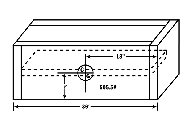
Symmetrical Weldment
WELDMENT 'B'
This weldment remains symmetrical, even after a 2-in-thick plate rib is added at the center
to create a rigid column.
• Added rib dimensions: 2 × 10 × 34 in
• Rib weight: 192.7 lb
• Total weldment weight: 505.5 lb
Because the added weight is centered and balanced equally in both directions,
the CG remains at the geometric center of the weldment.
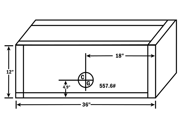
Unsymmetrical Weldment
WELDMENT 'C'
To form a box instead of a column, a 2-in-thick bottom plate is added to Weldment A.
• Bottom plate dimensions: 2 × 12 × 36 in
• Bottom plate weight: 244.8 lb
• New total weight: 557.6 lb
Because no material was added to the top to balance the added weight at the bottom,
the CG shifts downward. While the weldment remains balanced left to right and end to end,
the CG is no longer centered vertically and remains 18 in from either end.
UNDERSTANDING MOMENTS AND CG LOCATION
The center of gravity always moves toward added material. Determining its location is a function of moments, where a moment is defined as weight multiplied by distance (arm).
This is similar to a lever system and requires a reference plane. For tilt/turn positioners, the top surface of the table serves as that reference plane.
Load capacity tables are rated based on the distance the CG is above the table, making this reference especially useful. Whenever possible, weldments should be mounted with the heaviest side closest to the table.
How to Calculate Center of Gravity:
CG FORMULA:
1. Multiply the weight (W) of each component by its distance (D) from the table to determine its moment (lb-in).
2. Add all moments together.
3. Divide the total moment by the total weldment weight.

Example Calculation (Weldment 'C'):
Sides and Ends:
• Weight: 312.8 lb
• CG location: 8 in above the table
• Moment: 312.8 lb × 8 in = 2,502.4 lb-in
Bottom Plate:
• Weight: 244.8 lb
• CG location: 1 in above the table
• Moment: 244.8 lb × 1 in = 244.8 lb-in
Total Moment: 2,747.2 lb-in
Total Weight: 557.6 lb
Dividing the total moment by the total weight places the CG 4.9 in above the table surface.
Positioners enable welds to be made in the flat or slightly downhand position, where productivity, quality, and consistency are significantly improved.
Compared to vertical or overhead welding, properly positioned welds allow higher deposition rates, better appearance, and more reliable quality control,
while reducing operator fatigue and improving overall safety.
Selecting the right positioner ensures these benefits are fully realized. If you’re evaluating a specific weldment or application, our team can help review
your requirements and recommend the positioner configuration that best fits your needs.
Looking to Size a Different Positioner?
Check out our other guides on how to size the right positioner to fit your needs!