How to Size a Turning Roll
SELECTING A TURNING ROLL TO BEST MEET YOUR NEEDS
Turning rolls are designed to support and rotate cylindrical workpieces such as vessels, tanks, and pipe sections. Proper sizing requires evaluating weight capacity, rotation power, traction, and roll spacing to ensure safe and stable operation.
LOAD CAPACITY
The first step in selecting a set of Turning Rolls is determining the maximum weight capacity required to safely support your workpiece. Before evaluating how that weight is distributed, it’s important to understand how a basic Turning Roll system functions.
A standard Turning Roll system consists of:
• One powered Drive Roll
• One non-powered Idler Roll
The Drive Roll works to support one end of the workpiece, providing powered rotational motion, while the Idler Roll merely holds the workpiece, guiding the rotation from the opposite end. In a symmetrical application, the load is equally distributed between the Drive and Idler roller.
Each Drive and Idler roll has its own load rating and must be sized accordingly. Always determine the maximum total weight of the vessel before selecting a system.
TRACTIVE PULL, ROTATION RATING, AND ECCENTRIC LOADS
Tractive pull ratings indicate the available turning power of a Turning Roll that can be allotted during a given application. This turning power directly influences the rotation rating of the Drive Roll. In practical terms, it represents the Drive Roll’s capacity to rotate a smooth, round, straight-sided cylinder under load.
For Example:
A drive rated for 30,000 lb support may also be rated to rotate up to 90,000 lb, provided the load is properly distributed.
For a 90,000 lb vessel: (1) 30,000 lb drive roll and (2) 30,000 lb idler rolls may be required to provide both support and sufficient rotational power. In this example, load must be evenly distributed and contact all rollers throughout complete rotation.
Keep in mind:
• Vessel roundness
• Surface irregularities
• Roll alignment
These factors must be evaluted as all directly affect required rotation power.
Although most Turning Roll applications are primarily concentric loads, they are also rated to handle a certain degree of eccentricity. In applications involving eccentric loading, this available turning power must be compared to the force required to rotate the offset load to ensure proper performance.
To calculate the force required to
rotate an eccentric vessel:
The required force should never exceed 50% of the catalog-rated tractive pull.
Eccentric loading increases torque demand and can reduce drive performance if not properly sized.
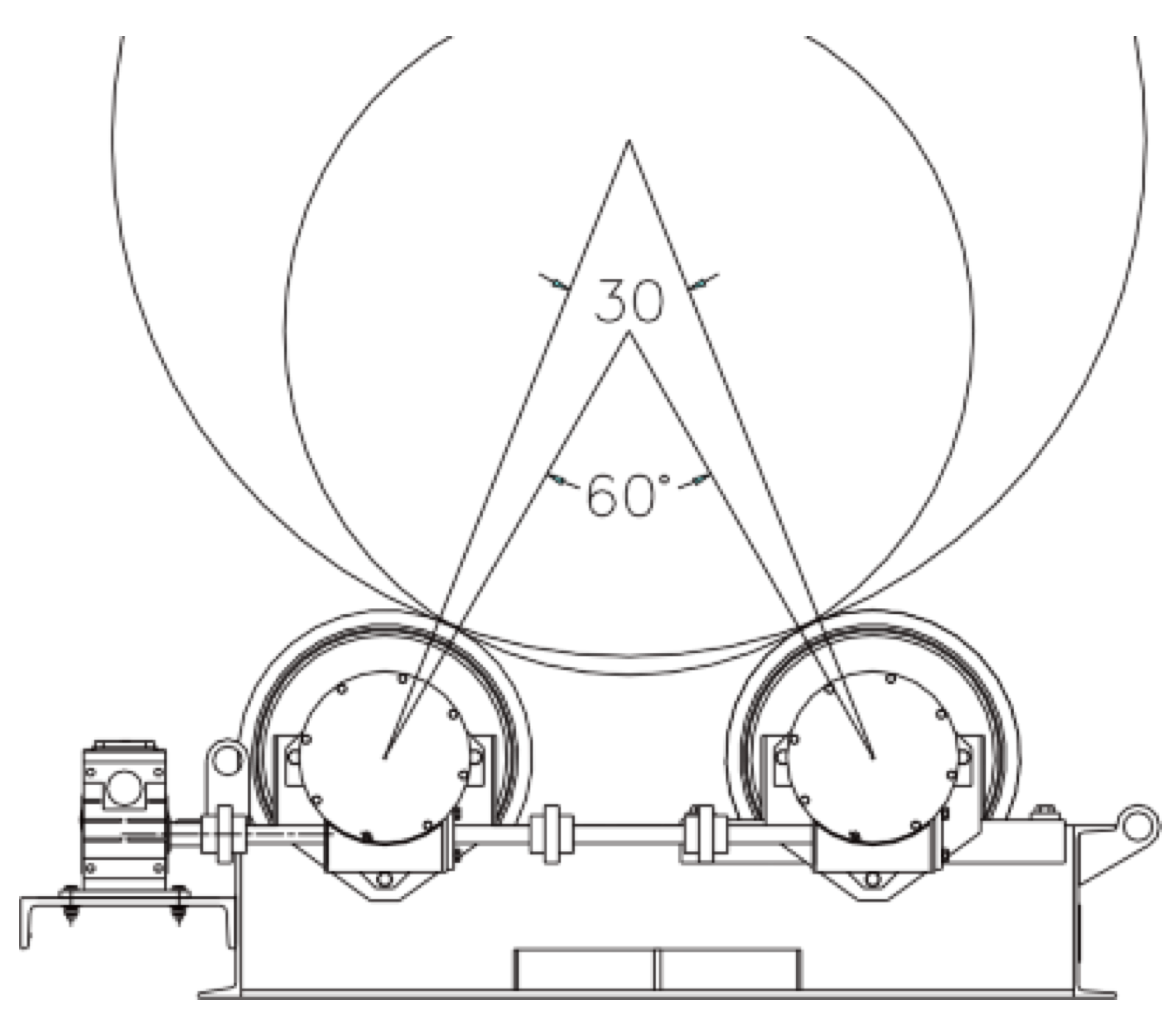
Included Angle (Roll Spacing)
The distance between rolls determines the included angle and directly affects stability and traction.
For Example:
For balanced, symmetrical loads:
Recommended included angle: 30°–60°
Considerations:
• Larger included angles increase traction but also increase torque demand.
• Small included angles can reduce stability and create unsafe conditions.
• The load must maintain continuous contact with all rolls throughout rotation.
Proper roll spacing is critical for smooth, controlled rotation.
Properly sizing a turning roll system requires evaluating weight distribution, rotation power, eccentric loading, and roll spacing. Understanding how these factors interact ensures safe operation, stable rotation, and long equipment life.
If you have a specific vessel size or application in mind, our team can help review your requirements and recommend the appropriate turning roll configuration.
Looking to Size a Different Positioner?
Check out our other guides on how to size the right positioner to fit your needs!