How to Size a Universal Balance
SELECTING A UNIVERSAL BALANCE TO BEST MEET YOUR NEEDS
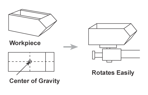
The Universal Balance Positioner allows a weldment to be mounted and manually rotated by hand around its own center of gravity. Selecting the appropriate Universal Balance model depends on the size and shape of the workpiece. The following descriptions and specifications provide a clear, logical checklist to help you select the right positioning equipment for your application.
Finding the Center of Gravity (CG) for the Rotational Axis:
As implied by its name, the core functionality of a Universal Balance Positioner relies on the perfect balance of a workpiece in relation to its table. To achieve this, the workpiece should be mounted on the positioner so that its CG aligns with the table’s rotational axis.
When properly balanced, the workpiece can be rotated around the axis with minimal effort. To prevent over-travel, our Universal Balance uses friction bands at the table’s rotation point, providing controlled resistance that allows the load to be smoothly positioned and held at any desired angle.
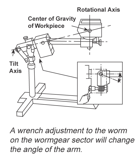
Finding the Point Intersection Between the Tilt and Rotational Axes:
To obtain balance between the tilt and rotation axes, the angle of the positioner's arm needs to be adjusted accordingly. The worktable of a Universal Balance is mounted at one end of this arm, with a worm and worm gear segment located at the opposite end.
Using the integrated worm gear, an operator can easily change the angle of the arm, allowing the tilt axis to intersect the rotational axis, aligning the workpiece’s CG in the third dimension.
When both axes intersect the CG, the workpiece can be moved by hand and positioned effortlessly at any angle, because it is in perfect balance.
Determining Load Capacity:
Universal Balance positioners are rated for overhanging loads from the table surface.
A typical rating is “1000 lb at 12 in (453 kg at 300 mm) CG height.” That means that the work-piece can weigh as much as 1000 lb (453 kg) when its CG overhang does
not exceed 12 in (300 mm) from the table surface.
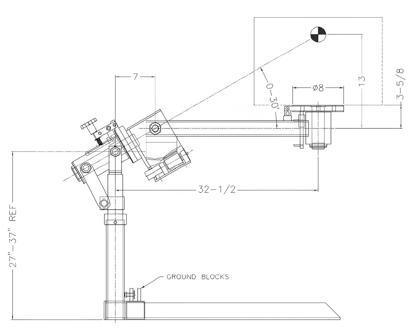
In the drawing, the CG symbol is shown at a distance of 13 in
(330 mm) above the centerline of the work arm. This represents the maximum
CG height that can be intersected by the tilt axis within the 30° adjustment range.
Because the distance from the tabletop to the centerline of the work arm is 3.625 in (92 mm), the effective CG height for balancing purposes is limited to 9.375 in (238 mm) above the table surface. Any CG located above this height will require the use
of counterweights.
It is important not to confuse the two separate CG considerations for Universal Balance positioners. One specification defines the maximum allowable load based on weight capacity. The CG shown in the illustration defines the maximum CG height that can be intersected by the tilt axis for a given model.
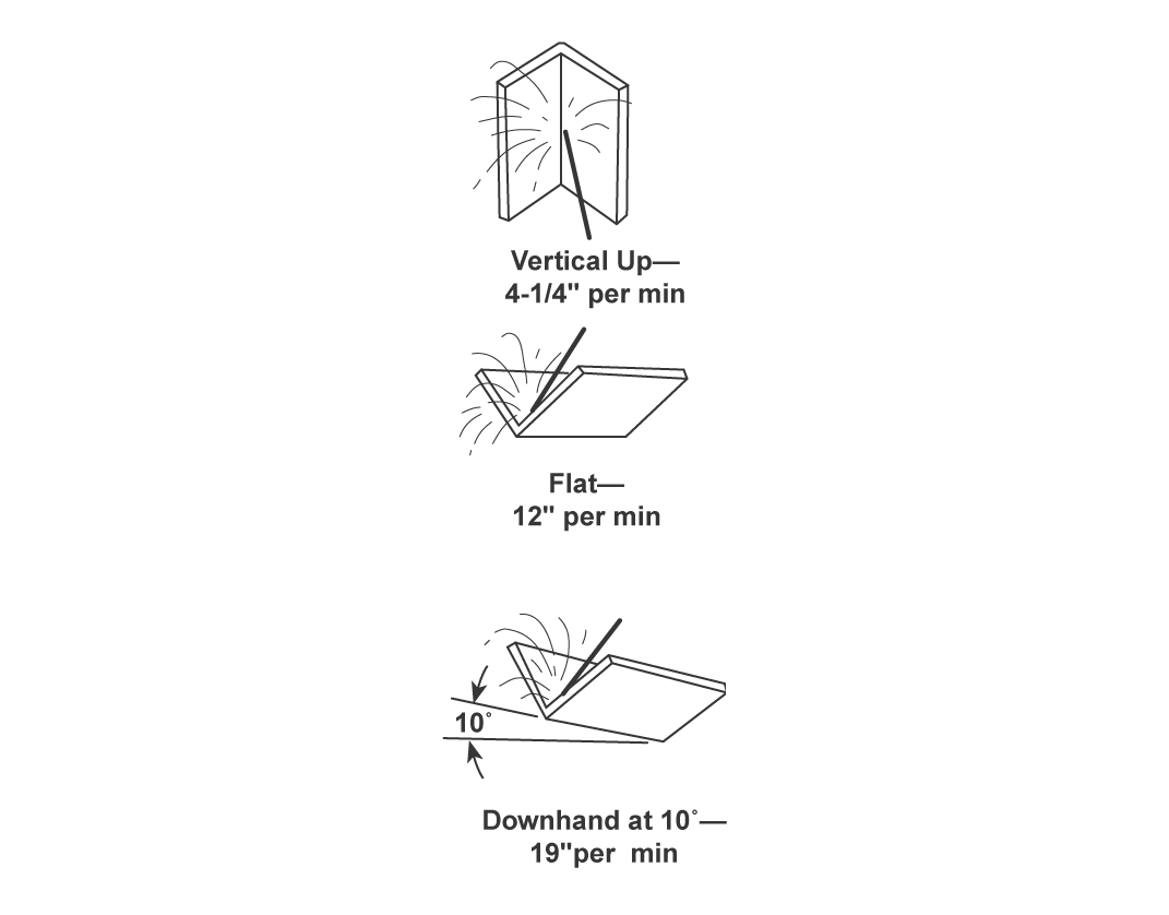
THE RESULT
With a properly calibrated Universal Balance, workpieces can be positioned smoothly and held securely, allowing welders to maintain the most productive
10˚ downhand position while increasing safety and reducing fatigue commonly associated with out-of-position welding.
By understanding how the center of gravity interacts with the Universal Balance, you can select and configure a positioner that provides stable control with minimal effort. If you have a specific application in mind, our team can help review your requirements and recommend the right model and configuration.
Looking to Size a Different Positioner?
Check out our other guides on how to size the right positioner to fit your needs!