How to Size a Manipulator
SELECTING A MANIPULATOR TO BEST MEET YOUR NEEDS
Selecting the correct manipulator for your intended application requires evaluating multiple factors including: lift, reach, load capacity, and track length.
LOAD CAPACITY
Manipulator load capacity must include all applied weight, not just the welding head.
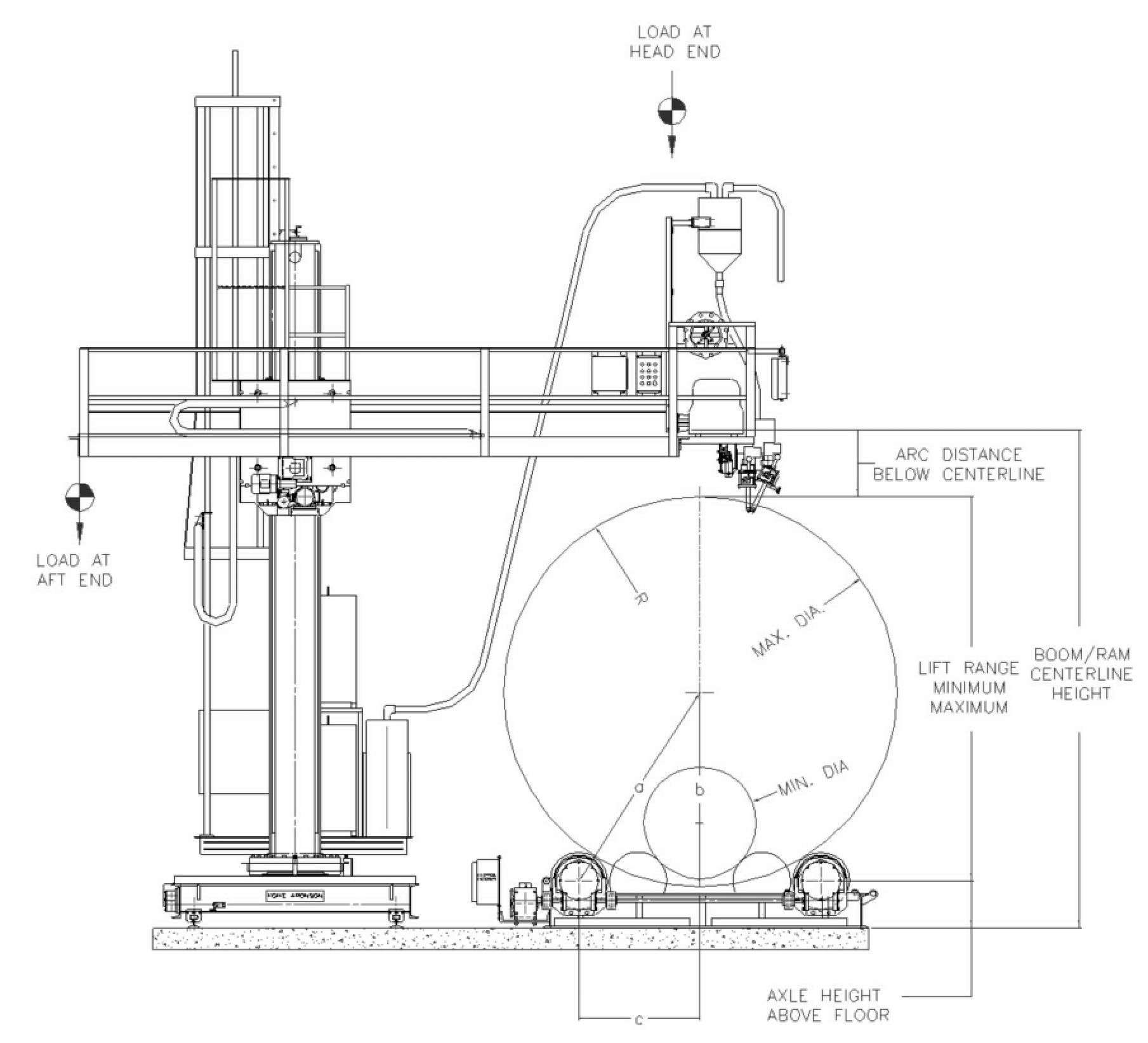
Load ratings are typically stated at:
• The head end of the boom
• The aft end
• Directly at the boom centerline
All additional loads must be included in calculations, such as:
• Welding equipment
• Operator platforms and seats
• Catwalks
• Cross slides
• All optional accessories
Load ratings vary depending on lift and reach configuration, so always reference the applicable load capacity table when finalizing selection.
LIFT AND REACH
Lift and reach requirements are determined by the most extreme vertical and horizontal arc locations required for the weld.
Dimensions are measured from the centerline of the mast (upright) and the boom (ram). The lift range defines vertical travel, while reach defines horizontal extension.
Together, they determine the total working envelope.
To calculate maximum lift required:
1. Determine the distance from the floor to the top of the vessel.
2. Solve for side “b” of triangle a-b-c using:
b = √(a² − c²)
3. Add: Axle height above the floor
• The vessel radius (R)
• The distance from the arc to the boom centerline
Repeat the process using the smallest vessel diameter to determine minimum lift requirements.
TRACK LENGTH (IF APPLICABLE)
When a travel car is used to move the manipulator longitudinally along a vessel, track length must also be considered.
To determine required track length:
• Add the length of the car frame to the total arc travel distance required.
Track sections are commonly available in 10 ft, 12 ft, 14 ft, and 16 ft lengths. Sections can be combined to achieve the required overall travel.
OPTIONAL EQUIPMENT AND ALTERNATE CONFIGURATIONS
Standard manipulators provide lift and reach capability only. Additional options must be specified based on application requirements, including:
• Travel cars and rail systems
• Operator seats and platforms
• Catwalks
• Cross slides
• Mast rotation
• Seam tracking systems
Properly defining these options ensures the manipulator is matched to both the welding process and production workflow.
Correctly sizing a manipulator requires understanding the full work envelope, total applied load, and required travel distance. When lift, reach, load capacity, and track length are properly evaluated, the result is stable positioning, accurate weld placement, and improved productivity.
If you have a specific vessel size or welding setup in mind, our team can review your application and recommend the appropriate manipulator configuration.
Need to Size a Different Positioner?
Explore our complete line of positioner sizing guides and find the right solution for your next application!